¶ Laser & Output Issues
¶ 1. P1 Laser Window Lens Is Stained or Damaged
- If stained: Wipe with 99% anhydrous ethanol or a professional optical lens cleaner (avoid cleaners containing ammonia or acetone), wiping gently in a single direction (e.g., from the center outward in a spiral) to avoid back-and-forth wiping that may cause scratches. After cleaning, inspect the lens surface under strong side lighting to confirm no residue remains. High-frequency users should clean once daily; low-frequency users once a week. See the P1 laser window lens & fan cleaning video.

Click to play video on YouTube
- If damaged: The window lens cannot be replaced separately — only the entire laser module can be replaced. Please provide customer service with clear photos of the damage, the machine's Serial Number, and the laser module's engraving code.


¶ 2. P1 Engraving Marks Become Faint
- Check focus: Refocus after placing the material — see the P1 laser focus adjustment tutorial video.
- Check material placement: The material must be placed flat; any dents, warping, or deformation can cause uneven depth.
- Check material type: Only opaque materials can be fully engraved — refer to the P1 parameter table to confirm whether the material can be engraved.
- Check software parameters: Set parameters according to the recommended parameter table; for materials without a recommended parameter, test multiple times yourself (you can reference parameters for similar materials).
- Check that the window lens is clean: Follow the same cleaning method described above (for a stained window lens).
- If the issue persists after these checks, please provide a screenshot of your settings, a video, a clear photo of the window lens, the machine's Serial Number, and the laser module's engraving code to customer service.
¶ 3. P1 Laser Cutting Performance Has Significantly Degraded
- Check usage duration: The laser module naturally loses power with extended use — this can be addressed by increasing power or reducing speed.
- Check focus: Refocus after switching to a material of a different thickness.
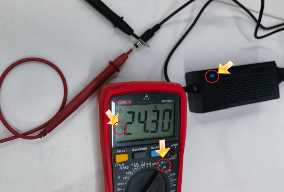
- Check adapter output: Use a multimeter (DC mode) to check whether the adapter outputs 20V–25V.
- Check software parameters: Verify your engraving parameters match the parameter table; LightBurn's maximum S-value of 1000 should not be modified.
- Check the window lens: Power off, remove the laser module, and check whether the window lens is dirty or damaged — clean if dirty, or replace the laser module if damaged.
- If none of the above resolves the issue, this indicates a laser module fault. Record a video of your troubleshooting process and provide it along with the machine's Serial Number and the laser module's engraving code to customer service for a replacement.


¶ 4. P1 Laser Module Moves During Operation, But No Laser Is Emitted
- Confirm you are not engraving a reflective material: If you need to engrave a reflective material, first coat the surface black, otherwise the laser module may be damaged.
- Check adapter output: Use a multimeter (DC mode) to check whether the adapter outputs 20V–25V.
- Check the laser connector: Unplug and reconnect the laser module's cable.
- Check recognition: AtomStack Studio automatically detects the laser module during operation. If it reports that no laser module is installed during framing or engraving, this may indicate a fault with the laser module or its cable — use a multimeter to check the cable for continuity. See the P1 laser cable measurement tutorial video.

Click to play video on YouTube
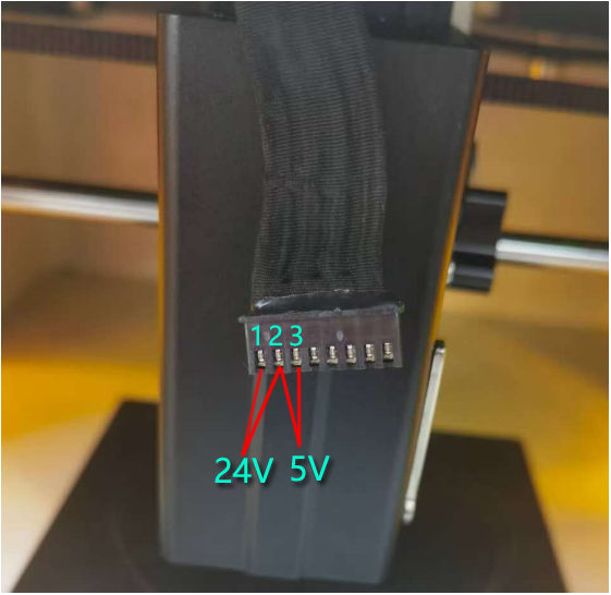
- Check the connector voltage: Run a cutting job at 100% power and 1mm/min, then use a multimeter to measure Pins 1-2 (should be 20V–25V) and Pins 2-3 (should be greater than 1V–6V). If normal, this indicates a laser module fault requiring replacement. Please provide a troubleshooting video, the machine's Serial Number, and the laser module's engraving code to customer service to arrange a replacement.
¶ 5. Using the 1.2W Infrared Laser, the Engraving Position Differs from the Framing Position
First perform crosshair calibration, then run framing and engraving again to see if the issue is resolved (see the P1 infrared laser crosshair calibration tutorial video — note that only the infrared laser module has a crosshair). If this doesn't resolve it, please refer to the "P1 frames normally, but crashes into the frame during engraving" section.
¶ Mechanical & Motion Issues
¶ 6. P1 Door-Opening Detection Function Fails
- Check the cable: The hall sensor board cable at the enclosure door may not be plugged in properly — unplug and reconnect it.
- Check the door is fully closed: Close the enclosure door again and retest.
- Check the door detection function is enabled: In AtomStack Studio or the mobile app, check whether "Door Detection" is turned on.
- Check the hall sensor: Bring a magnet close to the hall sensor at the enclosure door and observe whether the indicator changes from red to green. If the magnet triggers it but the door's own magnet does not, the door's magnetic strength is insufficient and it needs replacement. If it still doesn't trigger, the hall sensor itself is faulty and the hall sensor board needs replacement. See the P1 hall sensor board replacement video and the door detection on/off tutorial video (while waiting for a replacement part, you can temporarily disable door detection in the software/app).

Click to play video on YouTube

Click to play video on YouTube

¶ 7. P1 Engraving Output Is Irregular
- Check movement direction: Click the directional movement buttons in the software to move the machine and observe whether the direction matches; if abnormal or moving at a 45-degree angle, this may indicate a fault with a motor or the motherboard's motor driver — swap motor cables to determine which side the fault transfers to. See the P1 motor cable swap tutorial video and the motor replacement tutorial video.

Click to play video on YouTube

Click to play video on YouTube
- Check circle and square accuracy: Engrave a circle and a square in line mode, and observe whether the circle is fully closed and whether the square's four sides are equal in length.
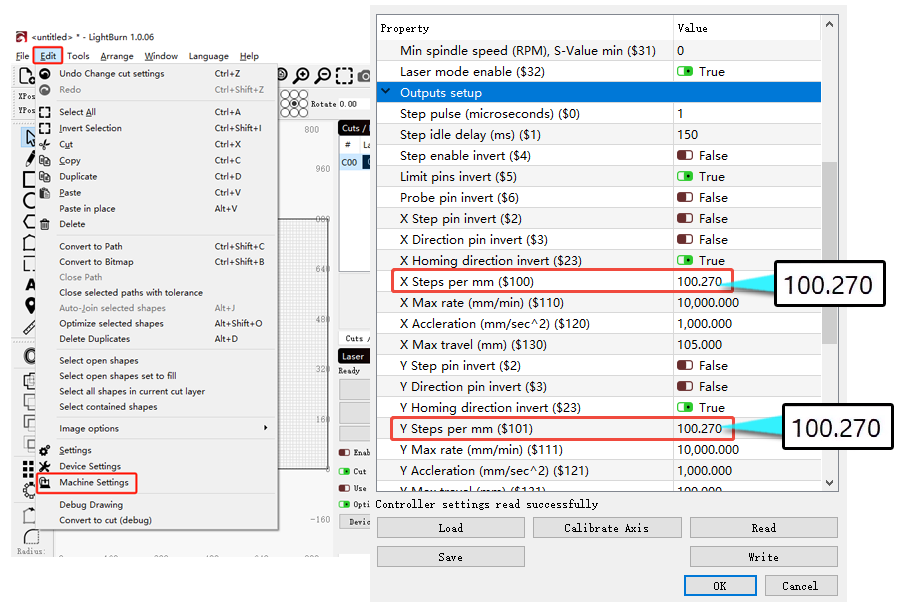
- If the lengths are inconsistent but the lines themselves are otherwise normal, the step-length parameter may have been changed — check $100 (should be 100.270) and $101 (should be 100.270) in LightBurn's Machine Settings.
- If the lines are wavy, uneven, or irregular, perform a structural adjustment first: check whether the timing belt is loose, whether it is properly seated in all guide pulleys, whether the X-axis is parallel to the top and bottom frame, and whether the motor pulley screws are tight. See the P1 structure adjustment tutorial video.

Click to play video on YouTube
- Check the firmware: If the structure and parameters are both normal, try reflashing the firmware. If this still doesn't resolve the issue, please provide a troubleshooting video, parameter screenshots, and the machine's Serial Number to customer service — a motherboard replacement may be needed.
¶ 8. P1 Keeps Displaying "Warn! Hit the limit." During Operation
- Check the laser module type: The infrared laser module has an engraving area of 105mm×100mm×50mm.
- Check the engraving file size: Verify it fits within P1's working area — adjust the file size if it exceeds this.
- Check the file coordinates: The file should not contain negative coordinates — reopen the software and re-import the file to test.
- Check the movement distance: Set up a 20×20mm square test engraving; if the actual dimensions don't match, the motor step length may have been changed (check $100/$101 in LightBurn — the standard value for both is 100.270) or there may be a motherboard control fault (try reflashing the firmware first; if this doesn't resolve it, it's a motherboard fault).
¶ 9. P1 Frames Normally, but Crashes into the Frame During Crosshair Alignment
- First perform crosshair calibration, then run framing and engraving again to see if the issue is resolved (only the infrared laser module has a crosshair).
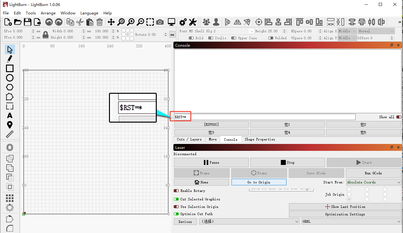
- If this doesn't work, enter
$rst=*in the LightBurn console, then perform crosshair calibration again. - If it still doesn't work, enter
$aux_red_light/offset_y_mm=0and$aux_red_light/offset_x_mm=0(or[ESP312]/X0/Y0) in the LightBurn console in sequence to reset the red crosshair offset, then calibrate again.
¶ 10. P1 Collides with the Frame During Engraving
- Check the file size: Verify it doesn't exceed the engraving area (blue laser 110mm×110mm, infrared laser 105mm×100mm).
- Check that framing is normal: You must frame before engraving — if the framing itself exceeds the frame boundary, engraving will also collide with the frame.
- Check the coordinates used: When using "Current Position," you must frame first to ensure there's enough space reserved for engraving; when using "Absolute Coordinates," as long as the file is smaller than the engraving area, collisions generally won't occur.
- Check the laser module type: The blue laser's engraving area is 110mm×110mm, with the origin point (0,0) at the homed position; the infrared (1064nm) laser's engraving area is 105mm×100mm, with the origin point (0,0) at the crosshair's center point.
- Check motor movement: Click the directional buttons to check whether movement is normal — if it only moves diagonally or triggers an alarm during engraving, check that the motor cables are properly connected.
- If none of the above resolves the issue, first check whether the firmware is up to date and update it; if already on the latest version, contact customer service for a previous version to try; if this still doesn't work, a motherboard and motor replacement may be needed.
¶ 11. P1 Makes a Clicking Noise During Operation and Moves at a 45-Degree Angle or Fails to Move
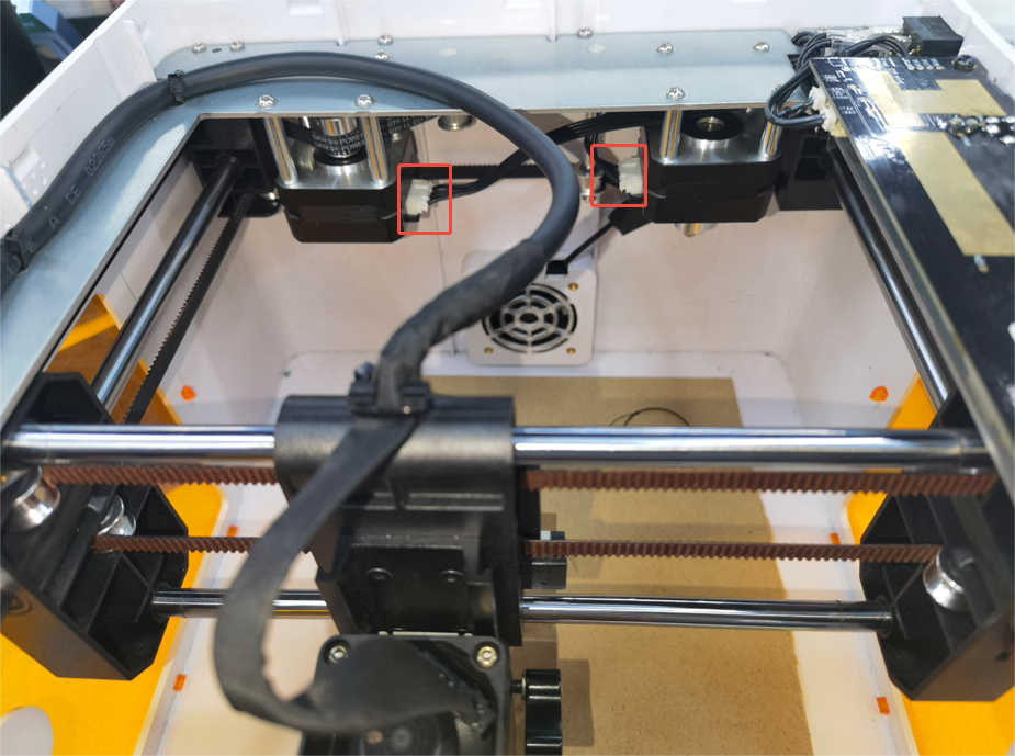
- Check the motor cables: Unplug and reconnect the motor cables to check they are properly seated.
- Check the motors: Unplug each motor individually to identify the faulty one, then swap motor cables to determine whether it's a motor fault or a motherboard driver fault — if the fault transfers with the cable swap to the other motor, it's a motherboard driver fault; if it doesn't transfer, it's a motor fault. See the P1 motor replacement and motherboard replacement tutorial videos.

Click to play video on YouTube
¶ 12. P1 Fails to Reset (Homing Failure)
- Check the limit switches: Manually press the X-axis and Y-axis limit switches and observe whether both trigger an alarm. If not, check the cable connections first; if this doesn't resolve it, the limit switch needs replacement.
- Check the motors: Click the directional buttons to move the X/Y axes and check whether movement is normal; if there's abnormal noise or no movement, refer to the "clicking noise" section above.
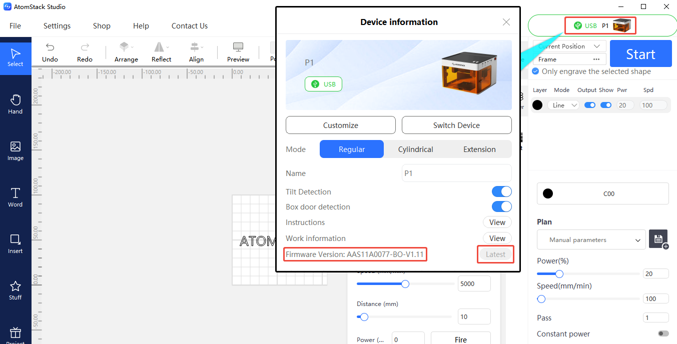
- Check the firmware: Check and update the firmware version via AtomStack Studio or the app (a USB drive must be inserted for the update).
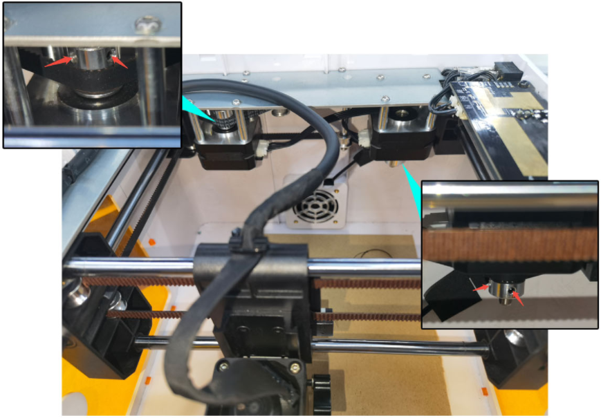
- Check the synchronization pulley tightness: Check whether both motors' synchronization pulley screws are tight, using the supplied 1.5mm hex wrench.
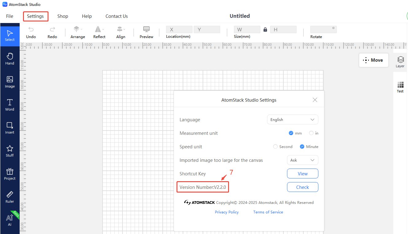
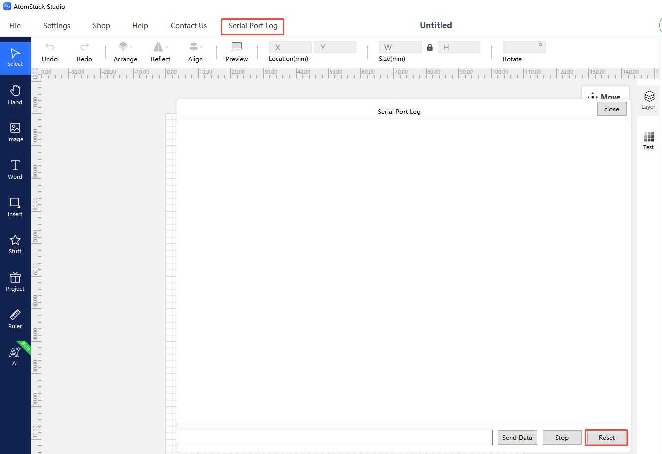
- Restore factory settings: If none of the above resolves the issue, you can restore factory settings via AtomStack Studio (version 2.20 or above — click the version number 7 times in a row to enter Developer Mode → Serial Port Log → Reset) or by entering
$RST=*in the LightBurn console.
¶ 13. Vector Lines Are Not Fully Closed at Both Ends During Engraving
- Check the focus: Loosen the L-shaped thumb screw securing the laser module, lower the focus rod until it touches the material surface, then re-tighten the L-shaped thumb screw.
- Check the power: If the engraving energy is too low, increase power or reduce speed.
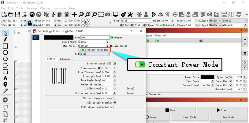
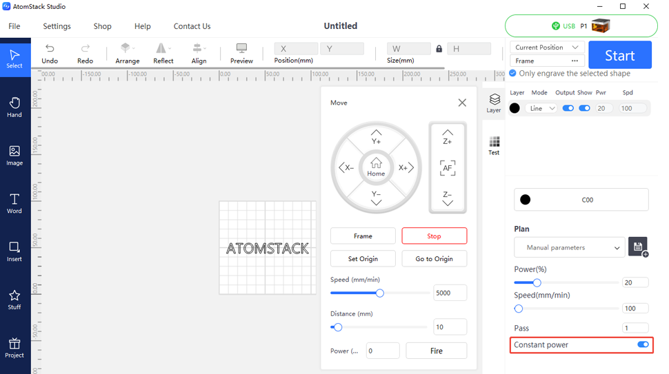
- Check constant power mode: Enable the "constant power" function in the software (available in LightBurn).
¶ 14. P1 Makes Unusual Friction Noise During Operation
- Check the linear guide rails: If the rail surface has become dry and lost its smoothness, apply lubricant.
- Check the timing belt: Check whether the timing belt is properly seated in each guide pulley's groove — if misaligned, it may rub against the spacer posts. See the timing belt replacement and guide pulley adjustment tutorial videos to correct this.

Click to play video on YouTube
- Check the motor step length: In LightBurn's Machine Settings, check whether $100 and $101 are set to the standard value of 100.270.
- Check the synchronization pulley screws: Use a 1.5mm hex wrench to check whether the motor synchronization pulley screws are tight.
¶ Connection, Power & System Issues
¶ 15. P1 Shows a Connection Failure When Connecting to Computer Software
- Check the panel indicator: Steady green is normal; red indicates an alarm state — check whether the enclosure door is closed properly, whether a limit switch is stuck in a triggered state (move the laser module to the center and try again), whether the USB key is plugged in, and whether the door limit switch is functioning normally. If you determine the limit switch is faulty, you can temporarily disable door detection in the software/app to keep working (please be careful with safety once disabled).
- Check your operating system: On a Mac, you cannot connect directly via the Type-C port — a USB hub is required to connect via the A port.
- Check the baud rate: LightBurn requires the baud rate to be set to 460800, or you can import the P1 configuration file.
- Check the COM port: Check Device Manager to see whether the engraver's serial port appears (plug/unplug the Type-C cable to observe the change). Install the driver if it's not recognized or shows a warning icon.
- Try a different cable and port: Try a different Type-C cable or computer COM port, or try switching to AtomStack Studio.
- If none of the above resolves the issue, this indicates a motherboard fault requiring replacement.
Driver downloads: Windows driver | Mac driver


¶ 16. P1 Mobile App Connection Fails
- Check Wi-Fi signal strength: If the signal is weak, refer to the "Weak Wi-Fi signal on the P1" section.
- Check no other device is occupying the connection: If another device is already connected to the engraver's Wi-Fi, your current phone won't be able to connect.
- Try a different connection method: P1 supports Wi-Fi, Bluetooth, and hotspot connection modes — try switching between them. See the P1 app connection tutorial video.
¶ 17. P1 Fails to Power On Normally
Indicator light shows steady red:
- Check whether the enclosure door is closed; check whether the hall sensor cable is loose by bringing a magnet close to the hall sensor to test whether it turns green. If the magnet can trigger it, the hall sensor cable is not properly connected or the sensor itself is faulty — see the "P1 door-opening detection function fails" section.
- Check that the laser module hasn't been moved to the extreme edge (which would continuously trigger a limit switch) — move it back toward the center and try again.
- Check that the enclosure's limit switches are not damaged: gently press each limit switch's lever to test whether it triggers an alarm sound.
- Check that the USB key connection is normal: gently touch the USB key to test for a poor connection — try unplugging and reinserting it, or pressing the plug in more firmly.
- Check the firmware: copy the firmware to the root directory of a USB drive, insert it into the engraver, and reflash.
- If none of the above resolves the issue, consider a motherboard replacement.
Indicator light shows steady green: The indicator is normal but it won't connect — please refer to the "P1 mobile app connection fails" section.
Indicator light alternates red/green with a beeping sound: This typically indicates a poor USB key connection — remove and reinsert it, or press the connector in more firmly.
Indicator light does not light up at all:
- Check that the power supply is normal: check whether the adapter's indicator light is on, and use a multimeter (DC mode) to measure whether the output is 20V–25V (below 20V indicates an adapter fault).
- Check that the power switch is functioning: disconnect power, open the top cover, and use a wire to briefly short the two power switch leads, then power on again to test — if it powers on, the switch is faulty.
- If shorting the switch still doesn't power the machine on, this indicates a motherboard fault requiring replacement.


¶ 18. P1 Suddenly Stops During Operation
- Check adapter output: Use a multimeter (DC mode) to check whether the adapter output is 20V–25V.
- Check the panel indicator: Observe whether a red alarm appears, and troubleshoot according to the alarm prompt.
| Alarm Prompt | Possible Cause | Troubleshooting Steps |
|---|---|---|
| Machine restart prompt | Motherboard fault, power adapter fault, or unstable mains power | ① Re-engrave to see if it recurs; ② Replace with a matching 24V 3A adapter; if it still recurs, this indicates a motherboard fault |
| Alarm 1 triggered, or "out of bounds" prompt | Not touching the frame: limit switch fault. Touching the frame: engraving file too large | ① Follow the software prompt to identify which limit switch was triggered; ② Inspect the limit switch's appearance; ③ Unplug/replug or manually trigger it to confirm whether it's faulty |
| Disconnection prompt | Type-C cable, COM port, or motherboard fault | ① Try a different Type-C cable and COM port; ② Install the computer's serial port driver; ③ If it still can't connect, this indicates a motherboard fault |
| No alarm prompt at all | Motherboard firmware or motherboard fault | Reflash the motherboard firmware; if this still doesn't resolve it, this indicates a motherboard fault |
¶ 19. Weak Wi-Fi Signal on the P1
- Check the Wi-Fi cable: Open the top cover and check whether the Wi-Fi antenna has come loose from the motherboard or is not properly connected — reconnect it.
- Check signal strength: If the signal remains weak after reconnecting, the Wi-Fi antenna itself is faulty — contact customer service to arrange a replacement. See the P1 Wi-Fi antenna replacement tutorial video.

Click to play video on YouTube
- Check the motherboard: If there is no Wi-Fi signal at all, this may indicate abnormal motherboard firmware or a motherboard fault — try reflashing the matching firmware first; if this doesn't resolve it, a motherboard replacement may be needed.

¶ 20. P1 Cannot Recognize the USB Flash Drive
- Reinsert it: Remove the USB drive, power off, then reinsert it and test again.
- Check the USB drive is functioning: Test it in a computer to confirm it can be recognized normally — if not, the USB drive itself is faulty.
- Check the USB drive's format: If prompted to format it, select the FAT32 format.
- Try a different USB drive: Insert a different USB drive into the machine to test.
- If the computer recognizes it and it has been formatted, but the issue persists, this indicates a fault with the motherboard's USB port, requiring a motherboard replacement.
¶ 21. P1 Is Interrupted When Using the Mobile App to Engrave, with an Error That the USB Drive Is Not Inserted
- Confirm it's properly inserted: Power off, then unplug and reinsert the USB drive.
- Check the USB drive's format: If prompted to format it, select the FAT32 format.
- Check the USB drive is functioning: Test it in a computer to confirm it's working normally.
- If this doesn't resolve the issue, the USB drive may be damaged — try replacing it.
¶ Accessories, Process & Other Issues
¶ 22. Inconsistent Engraving Results on P1 Despite Using the Same Parameters and Materials
- Check the focus is consistent: Readjust the focus after switching materials.
- Check the material is flat: Check whether the base plate is level and whether the material itself is flat.
- Check material grain/texture: Wood grain and texture can cause result differences — try a different piece, or test with MDF board instead.
- Check the window lens: A dirty lens will affect results — refer to the window lens cleaning section.
- Check for engraving distortion: Check whether the synchronization pulley set screws are loose, and whether the timing belt is properly seated in the guide pulleys.
- If the issue persists, please provide customer service with your settings/parameters, a description of the material's surface condition, a video of the engraving results, and a Serial Number photo.


¶ 23. P1 Engraving Result Is Unsatisfactory
- Check software parameters: Verify that appropriate engraving parameters have been set (see item 4 in the FAQ for how to access the P1 parameter table).
- Check the maximum S-value: LightBurn's maximum S-value should remain at 1000 and not be modified.
- Check the window lens: Power off and remove the laser module to check whether the window lens is dirty or damaged — clean if dirty, or replace the laser module if damaged.
- Check the voltage: Use a multimeter (DC mode) to check whether the power adapter output is 20V–25V.
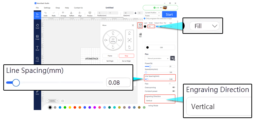
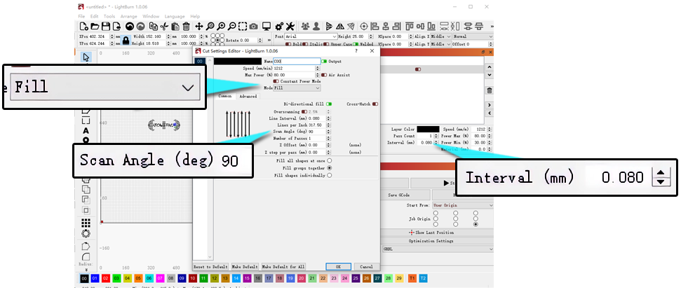
- Check line spacing and scan mode: If fill areas show horizontal banding, try reducing the line spacing to 0.08 and switching to vertical scan mode (available in both AtomStack Studio and LightBurn).
- Check for power degradation: Cut a piece of 3mm plywood once at 100% power, 200mm/min speed, and check for noticeable power degradation — replace the laser module if degradation is significant.
- If the issue is irregular patterns rather than poor quality, please refer to the "P1 engraving output is irregular" section.
¶ 24. When Processing Thin or Lightweight Materials, P1 May Experience Warping or Material Shifting
Solution: The enclosure fan's airflow may be too strong, causing the material to shift or warp upward. We recommend using the supplied magnets or other weights to secure the four corners or edges of the material.
¶ 25. Poor Smoke Extraction Performance of the P1 Enclosure Fan
- Check that the fan is clean: Excessive dust buildup requires cleaning first — see the enclosure cleaning & maintenance tutorial video.
- Check smoke extraction capability: If a purifier is connected, check whether the exhaust hose is kinked; try venting directly without the hose — if it works normally when venting directly, the purifier's filtration capacity has degraded and the filter should be replaced.
- Check whether the fan itself is faulty: If the fan speed remains too slow or it doesn't spin after cleaning, it needs to be replaced — see the enclosure fan replacement tutorial video.
¶ 26. Mirroring Occurs When Using Rotary Attachments on P1
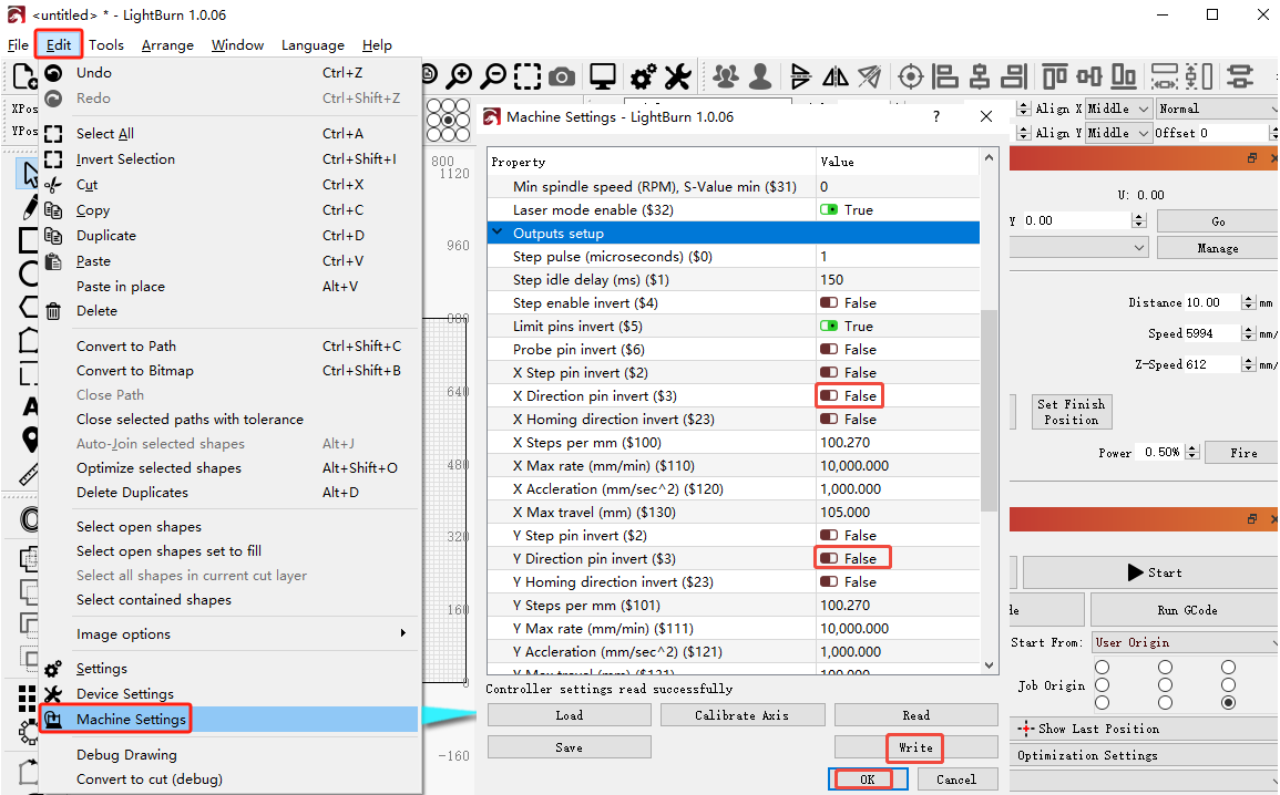
- Check the movement direction: Click the directional buttons and observe whether the movement direction is correct — if reversed, you can toggle the reverse axis $3 setting in LightBurn's machine settings.
- Check the firmware: If changing the parameter doesn't resolve it, reflash the motherboard firmware.
- Check the software settings: You need to configure the rotary parameters and toggle the mirror function on or off (available in both AtomStack Studio and LightBurn).
- If none of the above resolves the issue, a motherboard and X/Y-axis motor replacement may be needed.
¶ Other
¶ 27. After Turning on the P1, the Laser Cannot Be Moved Manually to the Desired Engraving Position
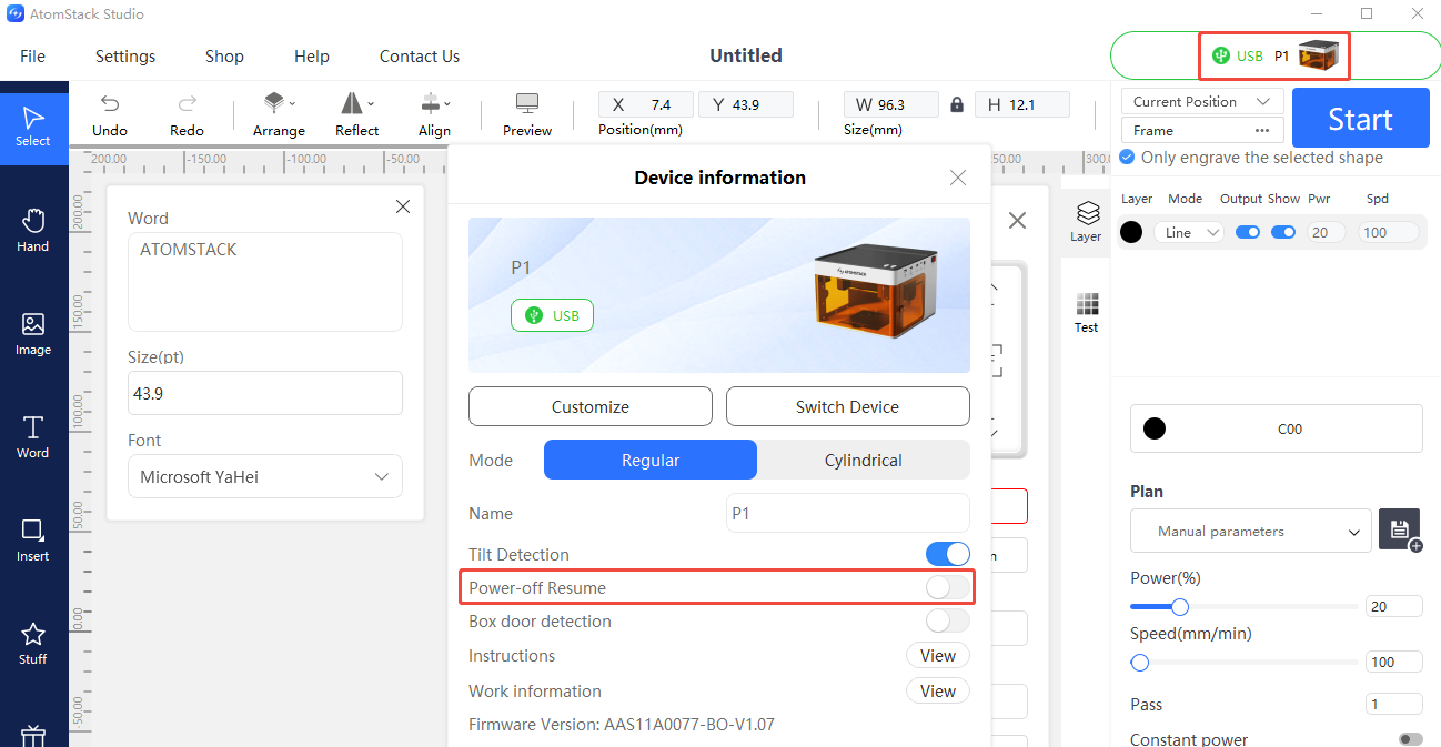
- Check that "resume after power loss" is not enabled: If it is enabled, you can disable "resume after power loss" after connecting via the AtomStack app or Studio.
- If the issue persists after disabling it, try reflashing the firmware first (the same firmware version cannot be reflashed twice — ask customer service for a different version). If it still cannot be moved after reflashing, but can be moved when powered off, this indicates a motherboard fault.
¶ 28. P1 Firmware Upgrade Failure
- Connect via AtomStack Studio or the mobile app and click to update the firmware (a USB drive is required as storage).
- If it still fails, first confirm whether the USB drive can be recognized by the engraver — if not, please refer to the "P1 cannot recognize the USB flash drive" section.
¶ 29. P1 Series Software, Firmware, and App Updates
- AtomStack Studio updates: The software will automatically prompt you if a new version is available when opened; you can also select "Check for Updates" in Settings, or download it from the AtomStack.com website.
- Firmware updates: Connect via AtomStack Studio or the mobile app and click to update the firmware (a USB drive is required); alternatively, copy the firmware file to the root directory of a USB drive and insert it into the machine to update.
- App updates: Download the latest version from the AtomStack.com website, or check the version and update from "Profile - Settings - About ATOMSTACK" within the app.
¶ 30. Software Alarm Prompts and Solutions
| Alarm Code | Description | How to Handle |
|---|---|---|
| Alarm 1 | Typically indicates a limit switch was triggered | If Alarm 1 occurs without hitting a limit switch, check each limit switch: trigger manually, and unplug/replug cables in sequence to locate the fault |
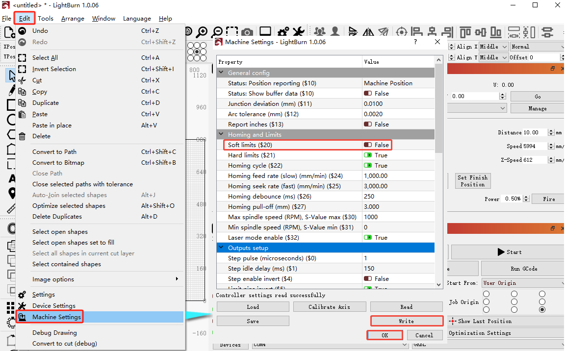
| Alarm 2 | Typically indicates a soft-limit alarm | Check whether $20 (soft limits) is enabled in the software's machine settings — disable it if so |
| Alarm 3 | Typically indicates an alarm triggered by a disconnection during operation | Investigate the specific cause based on the code prompt that appeared before the alarm |
| Alarm 8 | Typically indicates a limit switch stuck in a continuously triggered state | May indicate a damaged limit switch — unplug/replug cables in sequence to locate the fault |
| Alarm 11 | Typically indicates a tilt alarm | If the machine isn't actually tilted and the control box hasn't been removed, this may be a false alarm — try restarting, or disable the tilt alarm in the app / control panel / AtomStack Studio |