¶ 1. The Protective Window or Focusing Lens of the A70 Series Laser Has Stains or Damage
Solution:
- Inspect the protective window: after removing the protective window, wipe it with 99% pure anhydrous ethanol or a professional optical lens cleaner (avoid solvents containing ammonia or acetone). If stains or marks cannot be cleaned off, the protective window must be replaced. Refer to the 70W laser lens cleaning video for guidance.

Click to play video on YouTube
- Inspect the focusing lens: the focusing lens of the 70W series is non-removable. Do not attempt to pry or disassemble it yourself, as this may damage the laser's sealed structure. If the lens cannot be cleaned with alcohol and a lint-free cloth, or if the focusing lens is damaged, the entire laser unit must be replaced.
Note:
- Regular cleaning of the protective window helps prevent damage. If the focusing lens has uncleanable stains, marks, or damage, please provide clear photos of the damaged lens, the engraver's Serial Number, and the laser's engraved code to customer service for assistance.


Figure 6 Figure 7
¶ 2. Significant Decrease in Cutting Performance of A70 Series Laser
Solutions:
-
Normal power attenuation: after being used for a period of time, the laser may experience power attenuation within a normal range. Try increasing the power or reducing the speed to see if it can still operate properly.
-
Check operating environment: verify whether the ambient temperature exceeds 35°C. High temperatures can cause the laser to automatically reduce power during operation. Avoid continuous full-power operation for more than 4 hours; pause for 15 minutes every 2 hours when running at full power.
-
Check software settings: ensure that the engraving or cutting parameters in the software are set according to the parameter table. The S-value max in the software must remain at 1000 and should not be changed.

Figure 9 -
Inspect the protective window and focusing lens: check whether they are dirty or damaged. Refer to the "Protective window or focusing lens has stains or damage" section for detailed handling instructions.
-
Check for dust accumulation: examine whether the laser's fan and driver board have accumulated dust. Use a soft brush to clean off the dust. Refer to the 70W laser fan and driver board cleaning video.

Click to play video on YouTube
- Check air hood installation: verify whether the air hood is misaligned. Remove the laser from its mount and aim it at a wall more than 2 meters away. Use the fire button in the software to observe the laser spot — check if any part of the beam is blocked (a normal beam should display 7 rectangular strips). Refer to the 70W laser spot inspection video.
- If none of the above issues are found, the laser is likely faulty and needs to be replaced. Provide customer service with clear photos or videos of the troubleshooting process, along with the engraver's Serial Number and the laser's engraved code.
¶ 3. A70 Series Engraving Machine Can Move, But the Laser Does Not Emit Light
Solutions:
- Check software parameters: verify that the parameter settings in the software are correct, referring to the official parameter table.
- Ensure the material is not reflective: do not process reflective materials directly. Such materials must be coated black before use to prevent reflections from damaging the laser.
- Check laser cable connection: confirm that the laser's cable is properly connected. Turn off the power, unplug the laser cable, and then plug it back in securely.
- Measure cable voltage: turn off the power and unplug the 3-pin laser cable. Set a multimeter to DC mode, then run a cutting program at 100% power. Measure the voltage at the 3-pin connector: if the reading between pins 1 and 2 is 30V–37V, and between pins 2 and 3 is 1V–6V, the mainboard and cable are functioning normally. If the voltage between pins 1 and 2 is less than 30V, this indicates a power supply component failure. If the voltage between pins 2 and 3 is 0.1V–1V, this indicates a mainboard failure. Refer to the 70W laser cable voltage measurement video and the 70W mainboard replacement video for further instructions.

Click to play video on YouTube

Click to play video on YouTube

Figure 12
- If the laser cable voltage test shows no issues: open the back cover of the laser and remove the driver board. Unplug the two diode wires from the driver board. Then run an engraving program and observe the LED indicator next to the diode terminals on the driver board: if the LED lights up, the issue is a laser diode failure; if it does not light up, the issue is a driver board failure. Refer to the 70W laser driver board troubleshooting video and the 70W driver board and fan replacement video for detailed guidance.

Click to play video on YouTube
¶ 4. A70 Series Engraver Suddenly Stops During Use, Works Again After Restart, Then Stops Again While Engraving
Solutions:
-
Check TYPE-C cable connection: unplug and reconnect the TYPE-C cable to ensure it is securely connected.
-
Verify computer operating system: are you using Windows 11? If so, note that the control software must not be allowed to run in the background, as this can lead to interruptions or low-power operation.
-
Check software status: when the machine stops, check if the progress bar in the software is still moving. If yes, this could be caused by a disconnection issue — try cleaning the USB port on the engraver's control box, replacing the TYPE-C cable, trying a different USB port on the computer, or testing with AtomStack Studio software (official download: https://atomstack.com/pages/atomstack-studio-software).
-
Measure power supply voltage: use a multimeter in DC mode to check whether the power supply outputs voltages of 20V–25V and 30V–37V.

Figure 13 -
Check firmware: try re-flashing the firmware. Please contact customer service to obtain the correct firmware version, providing the Serial Number of the engraving machine. Refer to the firmware flashing video for step-by-step instructions.

Click to play video on YouTube
- If none of the above issues are resolved, the mainboard may be faulty and needs to be replaced. Refer to the 70W mainboard replacement video for guidance.
¶ 5. A70 Series Engraving Machine Stops Emitting Laser at Certain Positions During Operation, but Movement Continues
Solution:
Check whether the laser resumes emitting when the machine moves back from that position. If the laser emits normally after returning, this indicates a mainboard connection cable fault. In this case, the mainboard connection cable needs to be replaced.
¶ 6. A70 Series Engraving Machine Autofocus Failure
Solutions:
-
Check whether the Z-axis can move: in AtomStack Studio or LightBurn software, click the Z-axis movement control buttons and observe whether the Z-axis of the machine moves correctly in the indicated direction.

Figure 14
Figure 15 -
Check Z-axis operation during autofocus: if the Z-axis gets stuck midway, first perform Z-axis mechanical adjustment. If the issue persists after adjustment, it indicates a Z-axis motor failure, and the Z-axis motor needs to be replaced. Refer to the Z-axis mechanical adjustment video and the Z-axis motor replacement video for guidance.

Click to play video on YouTube

Click to play video on YouTube
- Inspect upper and lower limit switches: during the autofocus process, if the Z-axis reaches the top or bottom limit but does not reverse, this may be caused by a limit switch malfunction. Manually press the Z-axis upper limit switch and the laser lower limit switch, and observe whether an alarm or warning is triggered. If no warning appears, check for broken wires on the limit switch and inspect the PCB board near the mounting screw for paint loss or scratches, which may cause a short circuit. If no visible issues are found, the limit switch is likely faulty and needs to be replaced. Refer to the Z-axis upper limit switch replacement video and the 70W driver board and fan replacement video for detailed steps.

Click to play video on YouTube


Figure 16 Figure 17
- Check the Z-axis motor: if the Z-axis motor vibrates slightly but the laser module does not move, this indicates a Z-axis motor failure. Refer to the Z-axis motor replacement video for repair instructions.
- If the Z-axis can only move up or only down, this suggests a mainboard or mainboard connection cable failure. Refer to the 70W mainboard replacement video and the mainboard cable replacement video for further troubleshooting and replacement steps.

Click to play video on YouTube
¶ 7. Abnormal X-Axis or Y-Axis Movement on A70 Series Engraving Machine
Solutions:
-
Check axis movement via software: use AtomStack Studio, LightBurn, or LaserGRBL software to click the directional movement buttons (up, down, left, right) and observe whether the other axis moves normally.

Figure 18
Figure 19
Figure 20 -
Inspect motor cable connection: if the other axis moves correctly, check the motor cable of the abnormal axis for issues such as bent pins, broken pins, or other visible damage. If no abnormalities are found, reconnect the motor cable securely and test again.
-
Check for motor damage: if the issue persists after reconnecting, the motor itself may be faulty. Remove the X-axis cable track (tank chain) and swap the motor cable of the X-axis with the Y-axis motor port on the mainboard, then test the movement. Refer to the 70W motor swap test video for detailed instructions. The following table provides a detailed troubleshooting guide:

Click to play video on YouTube
| Situation | Troubleshooting method |
|---|---|
| X-axis normal, Y-axis malfunctioning | Insert the X-axis motor cable into the Y-axis motor: if the Y-axis still cannot move, the Y-axis motor is faulty; if the Y-axis can move, the issue lies with the motor driver on the mainboard or the mainboard connection cable. Refer to: 70W Motor Replacement Video, 70W Mainboard Replacement Video, 70W Mainboard Connection Cable Replacement Video. |

Click to play video on YouTube
| Y-axis normal, X-axis malfunctioning | Insert the X-axis motor cable into the Y-axis motor: if the Y-axis motor does not move, the issue is with the motor driver on the mainboard or the mainboard connection cable; if the Y-axis motor still moves, the X-axis motor is faulty. Refer to: 70W Motor Replacement Video, 70W Mainboard Replacement Video, 70W Mainboard Connection Cable Replacement Video. |
| Both X-axis and Y-axis cannot move | Check the mainboard connection cables for any breakage or pinching inside the drag chain. If no abnormalities are found, the issue is likely with the mainboard. After connecting the machine, enter $RST=* in the code box of the software console and execute it. If this does not resolve the issue, try reflashing the firmware (contact customer service with the Serial Number to obtain the correct firmware version). Refer to the firmware flashing video for guidance. |
- If re-flashing the firmware does not resolve the issue, the mainboard and mainboard connection cable both need to be replaced. Refer to the 70W Mainboard Replacement Video and 70W Mainboard Connection Cable Replacement Video.
¶ 8. A70 Series Engraving Machine Cannot Connect to the Computer
Solution:
-
Check whether the correct COM port is selected in the software. You can find the COM port number of the engraver (USB-CH340) in the Device Manager on your computer.

Figure 21 -
Check the baud rate settings: the baud rate in the software must be set to 115200, and the added controller must be set to GRBL.


Figure 22 Figure 23 -
Verify COM port recognition: in Device Manager, plug and unplug the USB cable to check whether a COM port appears or disappears accordingly. If the engraver's COM port is not detected, install the appropriate driver (e.g., CH340 or FTDI).
Figure 24 -
Check if the machine is functioning properly: if both LightBurn and LaserGRBL cannot connect, try downloading and using the AtomStack Studio client.
-
Check the computer system: Mac computers cannot directly connect to the Type-C port on the Type-C cable — they must use a docking station or USB hub to convert and connect through the Type-A port on the Type-C cable.
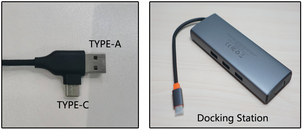
Figure 25 Figure 26 -
Check the connection cable and ports: try replacing the Type-C cable, switching to a different USB port on the computer, or using a different computer.
-
Verify the firmware status: try reflashing the firmware and attempt to reconnect.
-
If none of the above solutions work, the issue may be a mainboard failure, and the mainboard may need to be replaced. Refer to the 70W Mainboard Replacement Video for guidance.
¶ 9. Irregular Pattern Output on A70 Series Engraving Machine
Solution:
-
Identify the faulty axis: engrave a square and a circle outline to determine which axis is malfunctioning (or if both are). For example, use 10,000 mm/min speed, 30% power, and cutting mode on plywood to test square and circle patterns.
-
Inspect components for damage: carefully check the guide rails and rollers on the faulty axis for any damage. Ensure the timing belt tension is appropriate (refer to the 70W Structure Adjustment Video). Also check if the laser module bracket on the X-axis is loose or wobbly.

Figure 28 -
Check structural alignment: adjust the structure of the malfunctioning axis. After each adjustment, engrave a square and circle to see if the output improves. If there is improvement, continue adjusting; if not, no further adjustment is needed in that area. Refer to the 70W series Structure Adjustment Video.

Click to play video on YouTube
- Verify the X-axis alignment: if the lines are tilted but not wavy or curved, the issue is likely that the X-axis is not parallel to the lower beam. Adjust the X-axis to ensure it is parallel. Refer to the 70W series X-axis Parallel Adjustment Video.

Click to play video on YouTube
- Confirm the step length settings: if the output is just proportionally incorrect (with no bending, deformation, or offset), check whether the step values $100 and $101 have been changed from the default 133.33. Open LightBurn or LaserGRBL, go to the Edit menu, select Machine Settings, and check the values in the Outputs Setup section.
- If the step values are correct, contact customer support to obtain the appropriate firmware and reflash it.
- If none of the above steps resolve the issue, the problem may be due to a mainboard control failure, and the mainboard may need to be replaced. Refer to the 70W Mainboard Replacement Video for guidance.
¶ 10. Crosshair and Laser Dot Misalignment on A70 Series Engraving Machine
Solution:
Check the offset distance: all AtomStack products are calibrated at the factory. If the crosshair and laser dot are misaligned by more than 1 mm, recalibration is required. Refer to the 70W Crosshair Calibration Video for guidance.

Click to play video on YouTube
¶ 11. Frequent False Fire Alarms During Use of A70 Series Engraving Machine
Solution:
- Check the material: if the material is highly flammable (e.g., MDF or balsa wood), disable the flame detection function via the touchscreen, mobile app, or AtomStack Studio software. When cutting, use a higher speed, and for thicker materials, cut in multiple passes. Always supervise the machine during operation.
- Check the engraving file: if the engraving or cutting file contains dense line patterns, it may cause false fire alarms. Try increasing the speed, adding more passes, or disabling the flame detection function. The machine must always be supervised while in operation.
- Inspect the flame detection board: if fire alarms occur even at low power settings, the flame detection board may be faulty and needs to be replaced. Refer to the 70W Flame Detection Board Replacement Video for instructions.

Click to play video on YouTube
¶ 12. Rotary Keeps Spinning When Using the A70 Series Engraving Machine
Solution:
-
Check if auto-homing is enabled: ensure that the "Auto-home on startup" setting is disabled in the software.

Figure 29 -
Check if return to finish position is enabled: ensure that "Return to finish position" is also disabled when using a rotary roller.
-
Check if "Start from Absolute Coordinates" is selected: the engraving mode in the software should not use absolute coordinates when operating with the rotary.

Figure 30
¶ 13. A70 Series Engraving Machine Collides with Frame During Boundary Tracing or Engraving
Solution:
- Check file size: ensure that the file is within the engraving area and does not contain negative coordinates.
- Confirm actual engraving range: note that if auxiliary positioning (using the crosshair center as the laser start point) is enabled, the engraving area will be reduced.
- Check for software issues: try connecting with AtomStack Studio to see if the issue persists. If using LightBurn, make sure you are using a licensed version.
- Confirm correct machine movement: use the software to move the machine up, down, left, and right, and check whether the distance and direction are correct. If not, try flashing new firmware (contact customer support with the machine's Serial Number to obtain the correct firmware).
- Verify firmware status: if the movement distance and direction are correct, try reflashing the firmware anyway, using the correct version. Refer to the Firmware Flashing Video for guidance.
- If none of the above solutions work, the issue may be caused by a faulty mainboard. Contact customer support and provide the Serial Number to confirm the correct mainboard version. Refer to the 70W Mainboard Replacement Video for instructions.
¶ 14. Laser Module Emits Light but Fan Does Not Spin on A70 Series Engraving Machine
Solution:
- Check for obstructions: inspect the fan for any physical blockages or foreign objects. Manually spin the fan blades to check if dust, tangled wires, or a seized bearing is preventing movement. Clean the fan, and if it uses an oil-bearing type, apply a small amount of lubricant.
- Check fan wiring connection: open the laser module's rear cover and inspect whether the fan connector is properly plugged in. Unplug and replug the fan cable to see if it resumes operation. Refer to the 70W Driver Board and Fan Replacement Video for disassembly guidance.

Click to play video on YouTube
- Check for component failure: remove the fan and use two extra wires to connect it directly to a 24V adapter. If the fan still does not spin, the fan is faulty; if the fan spins normally, the driver board is faulty. Refer to the 70W Driver Board and Fan Replacement Video for instructions.
¶ 15. A70 Series Laser Power Mode Indicator Light Does Not Turn On
Solution:
- Check operating status: the power mode indicator light only turns on when engraving or cutting is in progress.
- Check switch functionality: if the power switch itself functions normally (i.e., it successfully changes power modes), the indicator light may be faulty, and the power mode switch should be replaced. Refer to the 70W Power Mode Switch Replacement Video. If the power switch does not function, continue with the following steps.

Click to play video on YouTube
-
Check wiring connection: inspect whether the power switch cable is properly connected. Open the laser module's rear cover, unplug the power switch cable from the driver board, then plug it back in. If the issue persists, the switch may be faulty — use a multimeter to test continuity between the two switch positions. If both the switch and cable are normal, the issue may be with the driver board. Refer to: 70W Driver Board and Fan Replacement Video, 70W Power Mode Switch Replacement Video.

Figure 32
¶ 16. Loose Laser Module Mount on A70 Series Engraving Machine
Solution:
- Check the slider assembly: first try tightening all screws, including those on the guide wheels and the eccentric nuts on the slider. Refer to the 70W X-axis Slider Adjustment Video for guidance.
- If the issue cannot be fixed by adjustment, or if it persists after adjustment, the X-axis slider needs to be replaced. Refer to the 70W X-axis Slider Replacement Video for instructions.

Click to play video on YouTube
¶ 17. A70 Series Engraving Machine Homes in the Wrong Direction and Does Not Return to (0,0) in the Lower Left Corner
Solution:
-
Verify motor direction settings: modify the value of $23 in the Machine Settings of the control software. If it is currently enabled, set it to disabled; if it is disabled, set it to enabled.

Figure 33 -
Confirm that no other parameters were modified: if the above settings do not resolve the issue, try restoring the factory defaults by entering $RST=* in the console command box. If restoring to factory settings does not solve the problem, reflash the firmware (contact customer support with the Serial Number to obtain the correct firmware version).

Figure 34
¶ 18. A70 Series Engraving Machine Cannot Read USB Drive
Solution:
- Check if the USB drive is damaged: insert the USB drive into a computer to see if it is recognized and accessible. If it cannot be recognized, the USB drive is faulty — you can purchase a replacement locally or contact customer support.
- Check the USB drive format: if the included USB drive is not recognized, try formatting it (if possible). FAT32 is the recommended format.
- If the above checks are normal, the issue may be a USB port failure on the mainboard. In that case, the mainboard needs to be replaced. Refer to the 70W Mainboard Replacement Video for guidance.
¶ 19. Mobile App Cannot Connect to A70 Series Engraving Machine
Solution:
- Check the operation procedure: ensure that the connection process in the mobile app is performed correctly. Refer to the Mobile App Connection Video for guidance.

Click to play video on YouTube
- Confirm the app version is up to date: you can update the app within the software itself or download the latest version from the official website: AtomStack.com.
- Check the mainboard Wi-Fi: ensure your phone can detect the engraver's Wi-Fi network, which should appear as Engraver_***.
- Try a different mobile device: disable mobile data or use a different phone to attempt the connection. The engraver's Wi-Fi can only connect to one device at a time.
- If none of the above work, the issue may be with the mainboard, and it may need to be replaced. Refer to the 70W Mainboard Replacement Video for instructions.
¶ 20. Engraving Interrupted When Using Mobile App on A70 Series Engraving Machine — Error: "USB Drive Not Inserted"
Solution:
This issue is likely caused by a faulty USB drive. It is recommended to replace the USB drive — you may purchase one locally or contact customer support to request a replacement.
¶ 21. No Display on the Control Screen of A70 Series Engraving Machine
Solution:
- Check machine status: ensure the engraving machine powers on normally and can connect to the computer or app as usual.
- Check HDMI cable connection: if the machine powers on correctly, unplug and replug the HDMI cable connected to the control screen, or try replacing it with a new HDMI cable.
- Check control screen functionality: tap the screen and listen for touch sound feedback. If you hear sound but see no display, shine a flashlight on the screen to check for faint text or images — if something is visible, the issue is likely with the mainboard or HDMI cable; if there is no display at all, it could be a touchscreen or HDMI cable fault. Note: replacing the touchscreen requires contacting customer support and providing the Serial Number, as different touchscreen versions may be incompatible. Refer to the 70W Touchscreen Replacement Video for guidance.
¶ 22. After Turning On the A70, the Laser Cannot Be Moved Manually to the Desired Engraving Position
Solution:
- Confirm that power-off resume engraving is not enabled: when the power-off resume engraving function is enabled and you want to move the machine manually, turn off the "power-off resume engraving" function after connecting to the AtomStack APP or AtomStack Studio software. Refer to the 70W series engraving machine function on/off tutorial video.

Click to play video on YouTube
- Check wiring connection status: if you cannot move the machine through the software, first inspect whether the mainboard connection cables are properly plugged in, and check for any bent or broken pins at the connector ports. If everything appears normal, the issue may be with the mainboard — try flashing the firmware first (contact customer support with the Serial Number to obtain the correct firmware version). If reflashing does not resolve the issue, the mainboard may need to be replaced. Refer to the 70W Mainboard Replacement Video for guidance.
¶ 23. Weak Airflow and Loud Noise from the Air Assist on A70 Series Engraving Machine
Solution:
- Check the air hose condition: inspect the air assist hose for any kinks or bends that may obstruct airflow.
- Check airflow strength: turn the air assist speed adjuster to its maximum level, then disconnect the air hose from the laser module. Point the open end of the hose at a sheet of A4 paper or a cloth strip to observe how strongly it moves — this helps determine whether the air pump output is too weak. You can record a video of this test and send it to customer support for evaluation.
- Check for internal cleanliness: open the air assist unit and clean out internal dust, especially around the air intake vents of the two air pumps. Refer to the 70W Air Assist Cleaning Video for detailed instructions.

Click to play video on YouTube
- If cleaning does not improve the airflow, both air pumps may need to be replaced. Refer to the 70W Air Pump Replacement Video for guidance.

Click to play video on YouTube
¶ 24. Air Assist Does Not Turn On on A70 Series Engraving Machine
Solution:
- Check whether the air assist has been activated: the air assist connected via the 12V power cable will only activate during engraving or cutting operations.
- Check operating condition: while engraving, observe whether the air assist unit vibrates. If there is vibration but no airflow, it indicates an air pump failure, and the pump needs to be replaced. Refer to the 70W Air Pump Replacement Video. If there is no vibration, proceed with the following checks.
- Check power supply: if you have a 12V adapter, connect it directly to the air assist to test if it turns on. If not available, you can briefly use the 24V output from the engraver's power supply to test by plugging it into the air assist power input (do not exceed 30 seconds). If it still doesn't start, the speed controller is likely faulty and needs replacement. If it does start, continue with the next steps.
- Check mainboard power output: use a multimeter (DC mode) to measure the 12V output port on the control box during engraving or cutting — the voltage should read between 10V and 13V. Also check the air assist power cable for disconnection or damage. Refer to the 12V Output Testing Video for instructions.

Click to play video on YouTube
- If all of the above fail to activate the air assist, the speed adjuster is defective and should be replaced. Refer to the 70W Air Assist Switch/Speed Adjuster Replacement Video for guidance.

Click to play video on YouTube
¶ 25. A70 Series Engraving Machine Power Supply Has No Output
Solution:
-
Confirm the correct input voltage setting: there is a voltage switch on the side of the power supply unit, used to toggle between different input voltages. This must be adjusted according to the local mains voltage. If the switch is set to 110V but connected to a 220V power source, the power supply may be permanently damaged.

Figure 35 -
Confirm if there is output: after turning on the power switch, if the power indicator light turns on but there is no 30V–37V and 20V–25V DC output, the power supply module may be faulty. When measuring output, use a multimeter set to the DC voltage range.
-
Check the fuse and cable connections: if the power switch indicator does not light up after turning it on, first check whether the power cable is properly plugged into the power module, then inspect the fuse inside the power supply. If the fuse is damaged, replace it with the same type locally. The fuse specification is 15A, 250V.

Figure 36 -
If the power switch indicator does not light up after turning on the power, and both the power cable and fuse are confirmed to be normal, the power supply module is faulty. Please contact customer service for a replacement.
¶ 26. A70 Series Engraving Machine Displays Alarm 9 During Homing
Solution:
Alarm 9 typically occurs when the homing process fails. The main causes and troubleshooting steps are:
- Check limit switches: manually press the limit switches on the machine frame, the Z-axis upper limit switch, and the lower limit switch on the laser module. Observe whether a trigger notification appears. If one of them does not respond, check the limit switch wiring and whether the insulating coating on the mounting screw hole is damaged. If no issues are found, the limit switch may be faulty and needs to be replaced.
- Identify when the alarm occurs: the homing sequence starts with auto-focus on the Z-axis, then moves on to homing. If the alarm appears before auto-focus completes, it indicates a Z-axis malfunction — refer to the troubleshooting steps under "Autofocus Failure."
- If multiple alarms or errors occur, try refreshing the firmware. If the issue persists even after switching to AtomStack Studio software, it may be a mainboard failure — replace the mainboard if necessary (refer to the 70W mainboard replacement video).
¶ 27. Common Software Alarm Prompts and Solutions
Common alarms:
| Alarm | Meaning | Solution |
|---|---|---|
| Alarm 1 | Generally indicates limit switch triggered | If alarm 1 occurs without hitting the limit switches during normal operation, check each limit switch: manually press the trigger block and unplug the limit switch plugs one by one to see if alarm 1 continues to occur, in order to locate the fault point. |
| Alarm 2 | Generally indicates that the soft limit alarm has been triggered | Check whether the software has enabled soft limits. The $20 value in the control software's Machine Settings indicates soft limits. If it is enabled, turn it off. |
| Alarm 3 | Generally indicates a disconnection during operation | Refer to the code prompts to check what appeared before the alarm to solve the problem. |
| Alarm 8 | Generally indicates that the limit switch is continuously triggered | The limit switch may be damaged. Locate the fault point by unplugging the limit switch wires one by one. |
| Alarm 11 | Generally indicates that the engraving machine is tilted | If the machine is not tilted and the control box has not been removed, it may be a false alarm. You can solve the problem by restarting the machine or turning off the tilt detection function via the mobile app, control screen, or AtomStack Studio software. |
| Alarm 12 | Generally indicates that the engraving machine detected flames | Refer to the solutions under "Frequent False Fire Alarms During Use of A70 Series Engraving Machine." |
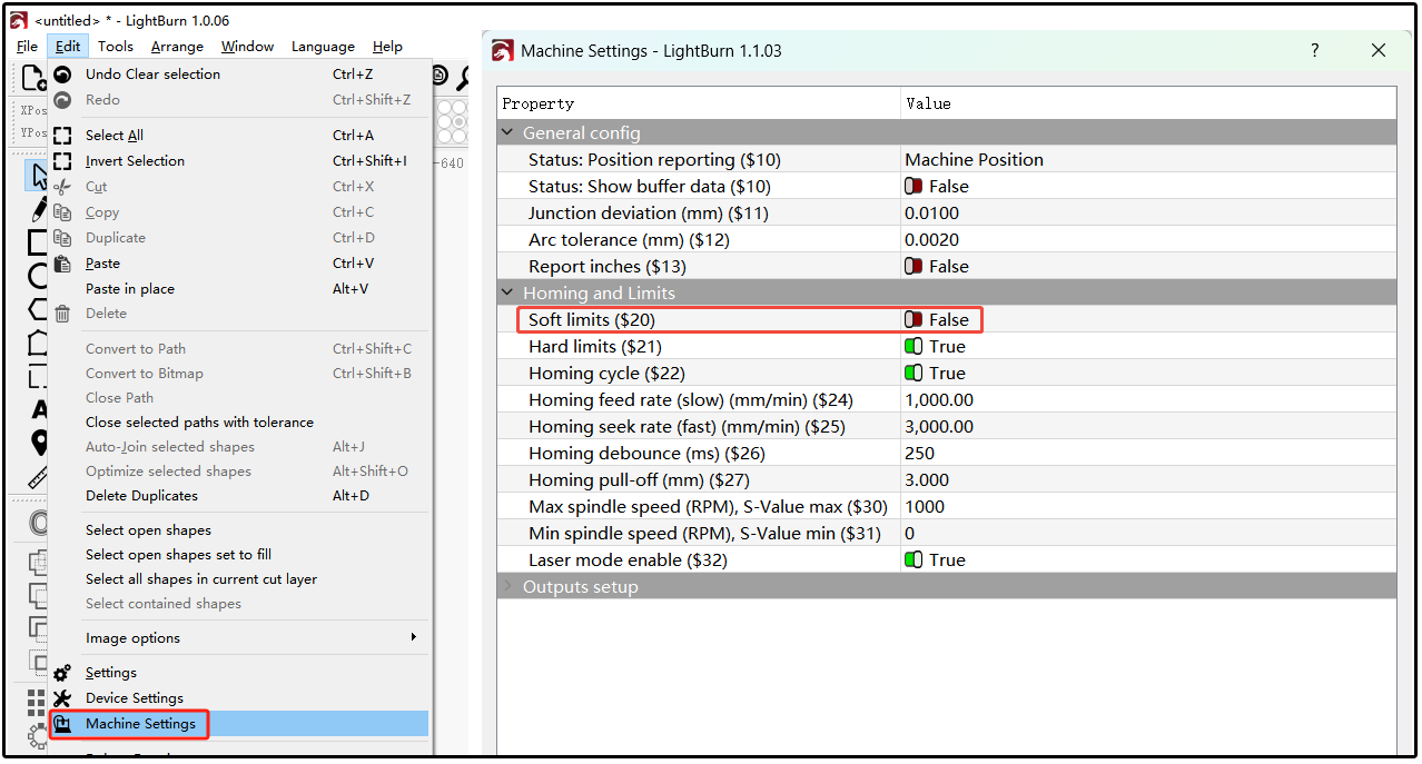
Figure 37
¶ 28. PC Software, Firmware, and Mobile App Updates for A70 Series Engraving Machine
- AtomStack Studio Software Update (PC): when opening the software, it will automatically prompt you if a new version is available. If no prompt appears, go to "Settings" > "Check for Updates". You can also download the latest version from the official website: AtomStack.com.
- Firmware Update: you can update the firmware directly through the AtomStack mobile app, or take a clear photo of your machine's Serial Number and send it to customer support to request the correct firmware, then copy the firmware file to the root directory of a USB drive to perform the update.
- Mobile App Update: download the latest version of the AtomStack app from AtomStack.com, or in the app, go to "Personal Center" > "Settings" > "About ATOMSTACK" to check the version — if an update is available, follow the prompts to update directly.